Arduino Uno Pin Layout - Arduino Nano To Arduino Uno Adapter 6 Steps With Pictures Instructables - Arduino uno r3 pcb resources easyeda.
Get link
Facebook
X
Pinterest
Email
Other Apps
Arduino Uno Pin Layout - Arduino Nano To Arduino Uno Adapter 6 Steps With Pictures Instructables - Arduino uno r3 pcb resources easyeda.. Laminate the sheet and punch. Easyeda arduino uno 3x3x3 led cube shield pcb layout download. But the recommended current is 20 ma. Arduino mega 2560 pin diagram The 14 digital input/output pins can be used as input or output pins by using pinmode(), digitalread() and digitalwrite() functions in.
Arduino nano pinout description the arduino nano pins, similar to the uno, is divided into digital pins, analog pins and power pins. At first you use mainly the pins in the female headers at Each stepper motor driver needs to be connected to the following pins:. The arduino uno pins compatible with pwm are the pins 3, 5, 6, 9, 10 and 11. In this post i'll give you a complete and practical overview of the main arduino uno pins.
Arduino Board Comparison Guide Arrow Com from static4.arrow.com Diy arduino uno v1.0 schematic design pcb layout. Similar steps are followed for the pcb layout as it is followed for schematic capture. Each pin can provide/sink up to 40 ma max. Nice drawings of the arduino uno and mega 2560. The new uno boards added a fourth mounting hole, which is indicated. The spi pins are also broken out on the icsp header, which is physically compatible with the arduino /genuino uno and the old duemilanove and diecimila arduino boards. Reference datasheet for atmega328 arduino uno r3 have 14 digital input/output pins (which include about 6 pins pwm output), 6 analog inputs and one 16mhz ceramic resonator, one usb connection and power jack, an icsp header (in circuit serial… This can be quite useful to control some actuators that require a fine voltage tuning, and are not only switched on or off.
Similar steps are followed for the pcb layout as it is followed for schematic capture.
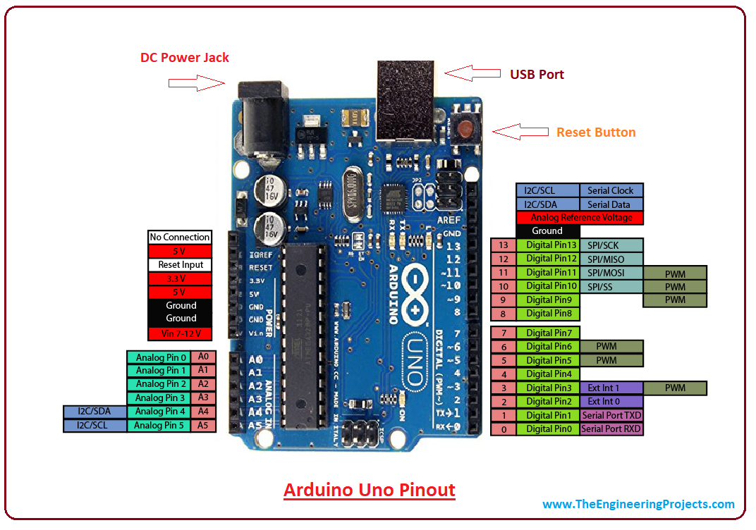
If you're looking to make your own shield for the arduino platform, you'll definitely need to know where all the pins and holes are located on the arduino. The arduino uno pins compatible with pwm are the pins 3, 5, 6, 9, 10 and 11. Pighixxx february 1, 2013, 2:07pm #2. Follow the diagrams below to connect the keypad to an arduino uno, depending on whether you have a 3x4 or 4x4 keypad: So you have 6 pins where you can create a pwm, using the analogwrite () function. When the pin is high value, the led is on, when the pin is low, it's off. Diy arduino uno v1.0 schematic design pcb layout. Reference datasheet for atmega328 arduino uno r3 have 14 digital input/output pins (which include about 6 pins pwm output), 6 analog inputs and one 16mhz ceramic resonator, one usb connection and power jack, an icsp header (in circuit serial… You can use it in your iot projects, wearable technologies and robotics projects. All power pins have a maximum current of 50 ma. In this post i'll give you a complete and practical overview of the main arduino uno pins. Below the layout of the pins on the arduino board. The pin mapping for the atmega168 and the 328p is roughly the same.
After doing a quick search, i was unable to find an accurate technical drawing of the new arduino uno. If you're looking to make your own shield for the arduino platform, you'll definitely need to know where all the pins and holes are located on the arduino. How to find the pinout of your keypad All the components are placed on the top side of the pcb. The 14 digital input/output pins can be used as input or output pins by using pinmode(), digitalread() and digitalwrite() functions in.
Introduction To Arduino Uno The Engineering Projects from www.theengineeringprojects.com Similar steps are followed for the pcb layout as it is followed for schematic capture. This can be quite useful to control some actuators that require a fine voltage tuning, and are not only switched on or off. Pighixxx february 1, 2013, 2:02pm #1. A 3d view / render of the pcb is also available in kicad. The nano has two more analog … In this post i'll give you a complete and practical overview of the main arduino uno pins. Pighixxx february 1, 2013, 2:07pm #2. All power pins have a maximum current of 50 ma.
Pighixxx february 1, 2013, 2:02pm #1.
They operate at 5 volts. The 14 digital input/output pins can be used as input or output pins by using pinmode(), digitalread() and digitalwrite() functions in. This article discusses about the technical specs most importantly the pinout and functions of each and every pin in the arduino. At first you use mainly the pins in the female headers at You can use it in your iot projects, wearable technologies and robotics projects. Each pin can provide/sink up to 40 ma max. The pin mapping for the atmega168 and the 328p is roughly the same. The board has 14 digital i/o pins (six capable of pwm output), 6 analog i/o pins, and is programmable. All the components are placed on the top side of the pcb. Easyeda arduino uno 3x3x3 led cube shield pcb layout download. The atmega328p microcontroller is the main chip of the arduino board. Pins 0 (rx) and 1 (tx). The chip used in arduino 2560.
Arduino uno r3 pcb resources easyeda. The pin layout for most membrane keypads will look like this: Nice drawings of the arduino uno and mega 2560. Below is the pin mapping for the atmega8, the original chip used in early arduinos. Arduino uno pins layout | if you're starting with arduino, or if you're already a software developer and want to learn more about the bridge between.
Touchdesigner Arduino Reactive Spaces And Media Architecture from arduinotogo.com Microcontroller section of diy arduino uno v1.0; Arduino zero is an advanced version of arduino uno. The nano has two more analog … The nano board weighs around 7 grams with dimensions of 4.5 cms to 1.8 cms (l to b). Layout of arduino uno board. The following image shows the layout of a typical arduino uno board. But the recommended current is 20 ma. Similar steps are followed for the pcb layout as it is followed for schematic capture.
The chip used in arduino 2560.
The drawing has dimensions for both the regular arduino and the arduino mega, and the hole pattern is good for all arduinos going back to the ng (though the diameter of the holes might be different). How to use arduino board. If you're looking to make your own shield for the arduino platform, you'll definitely need to know where all the pins and holes are located on the arduino. Easyeda arduino uno 3x3x3 led cube shield pcb layout download. The board has 14 digital i/o pins (six capable of pwm output), 6 analog i/o pins, and is programmable. A 3d view / render of the pcb is also available in kicad. The arduino uno pins compatible with pwm are the pins 3, 5, 6, 9, 10 and 11. The new uno boards added a fourth mounting hole, which is indicated. The nano has two more analog … Each of the 14 digital pins on the arduino uno can be used as an input or output using pinmode digitalwrite and digitalread functions. Arduino uno smd reference design in designspark pcb format. Each pin can provide or receive a maximum of 40 ma and has an internal pull up resistor disconnected by default of 20 50 kohms. This can be quite useful to control some actuators that require a fine voltage tuning, and are not only switched on or off.
When the pin is high value, the led is on, when the pin is low, it's off arduino uno. Davide gomba — january 5th, 2011.

Comments
Post a Comment